A liquid can take on the shape of its container, but can only fill the volume it can occupy.
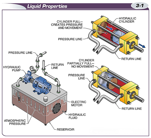
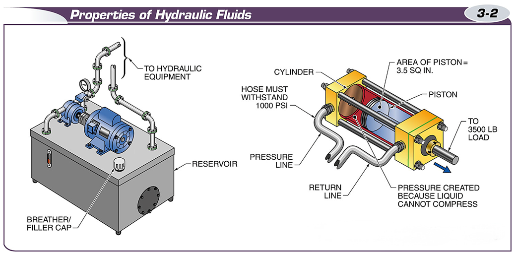
In a hydraulic system, fluid can transfer energy because it is almost completely incompressible.
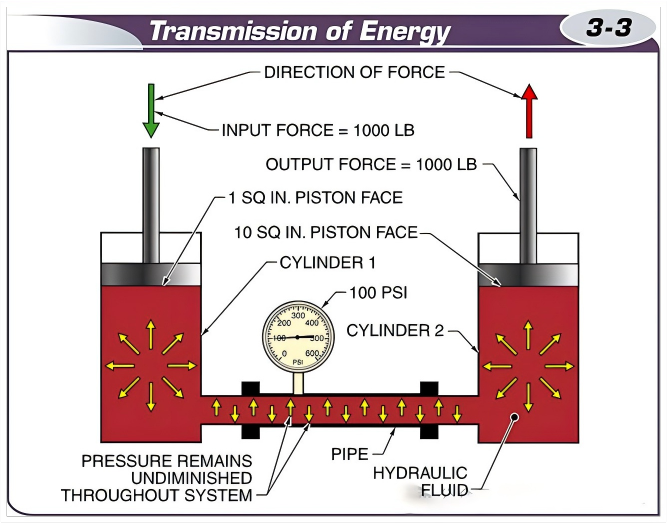
Pascal’s law can be applied during the energy transfer process in hydraulic systems.
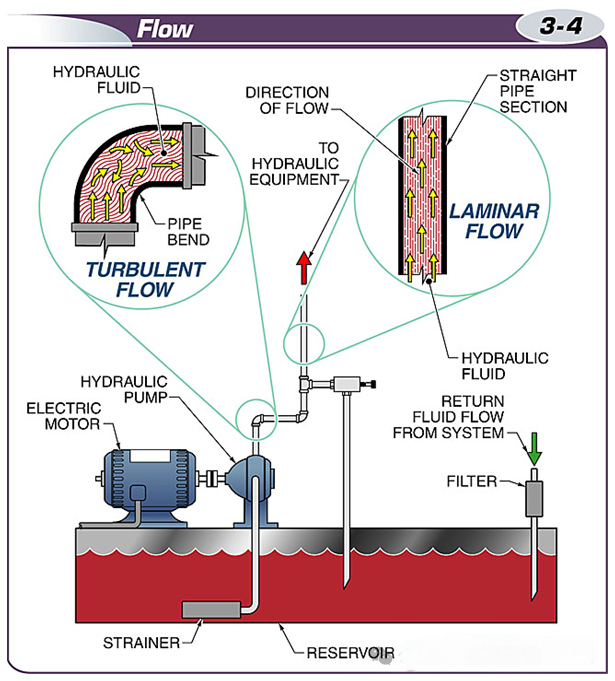
In fluid power systems, laminar flow is preferred over turbulent flow because it is more efficient and has less energy loss.
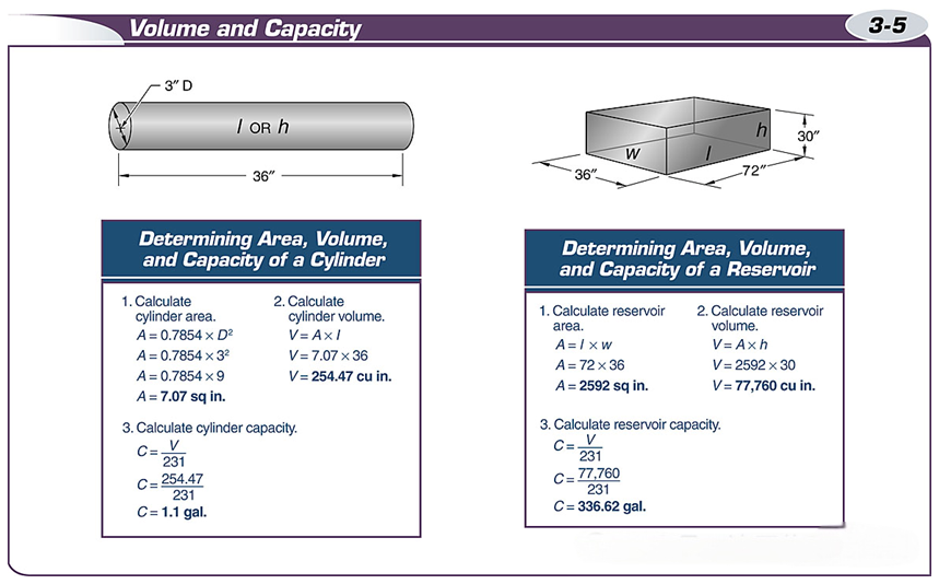
Volume is the three-dimensional space of an object, measured in cubic units.
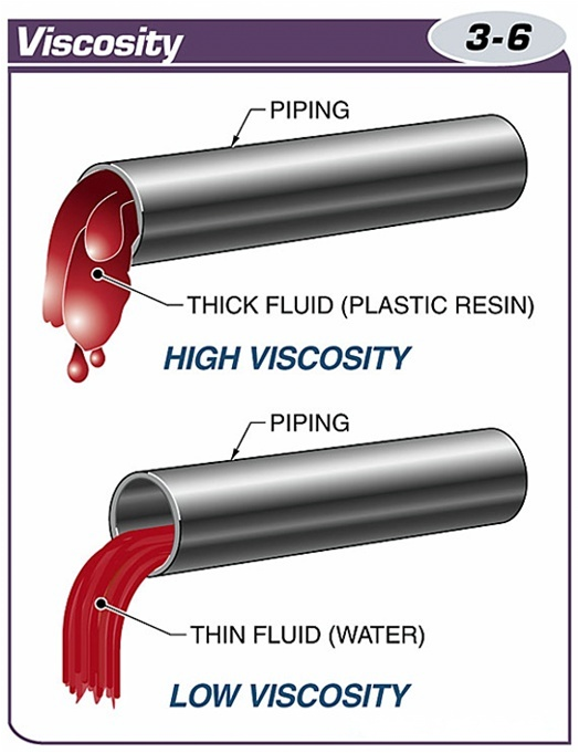
Fluids with high viscosity are thick and flow with difficulty, while fluids with low viscosity are thin and flow easily.
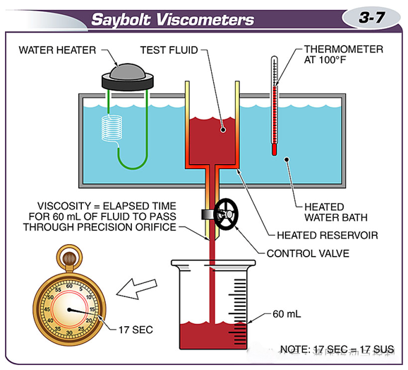
A Saybolt viscometer is a test instrument used to measure the viscosity of a fluid.
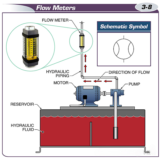
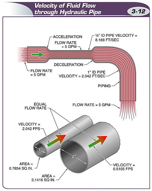
A flow meter is a meter used to measure the flow of fluid in a system in gallons per minute.
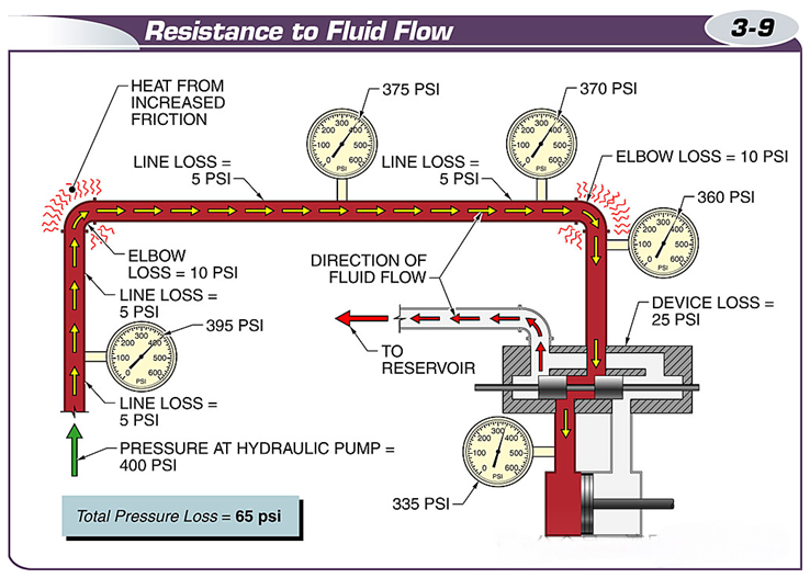
Resistance to the flow of a fluid creates friction, and the resulting energy is converted to heat.
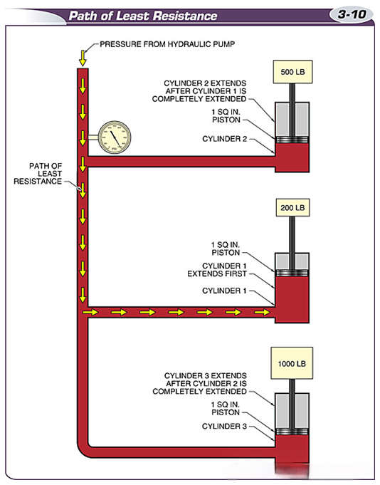
Fluid will follow the path of least resistance, so the cylinder with the least load will extend first.
Velocity is the speed at which the fluid moves through the hydraulic line, measured in feet per second.
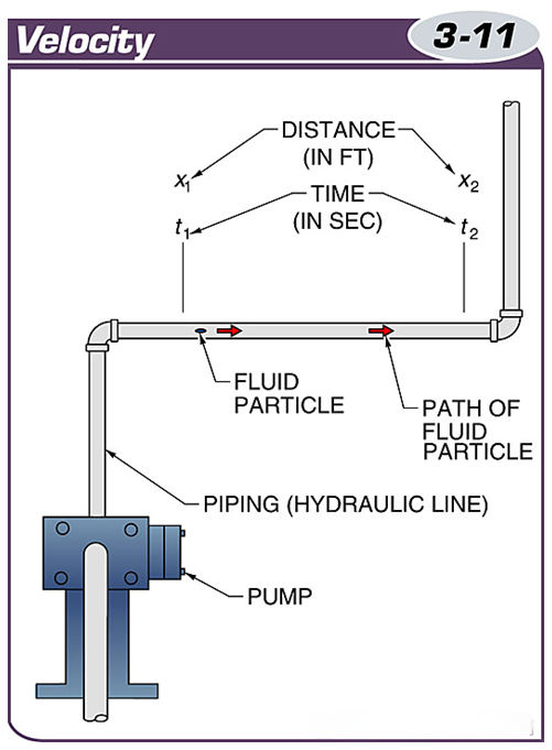
If the flow in the system remains constant, the velocity of the fluid will increase at any restriction in the pipe or component.
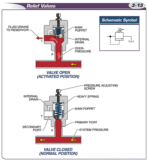
Relief valves set the maximum operating pressure of the hydraulic system.
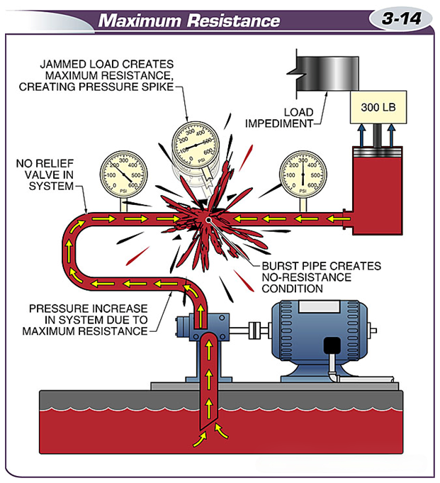
When resistance becomes too great, pressure increases until the weakest point in the system ruptures.
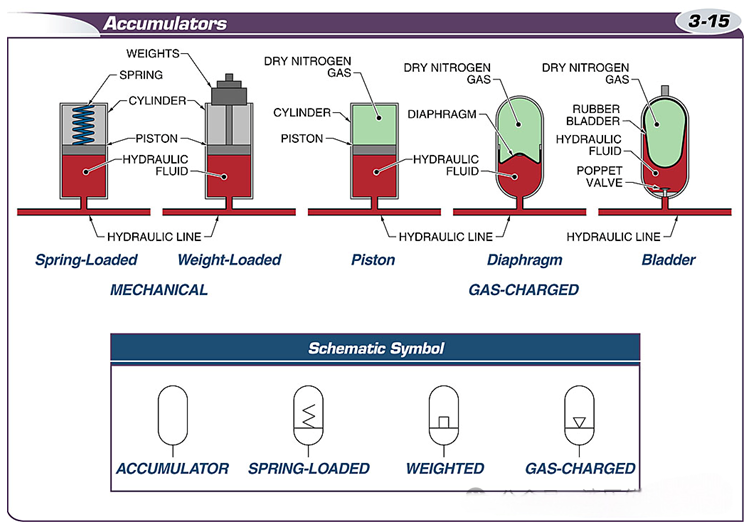
Accumulators are classified into two types: mechanical and pneumatic.
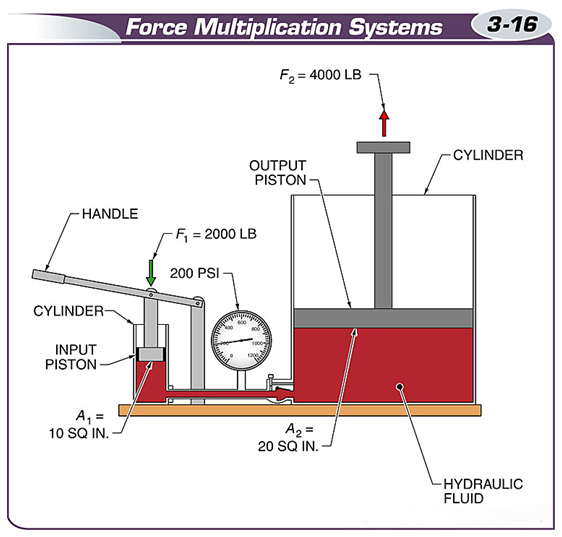
Force amplification systems can multiply the force applied to one cylinder by another.
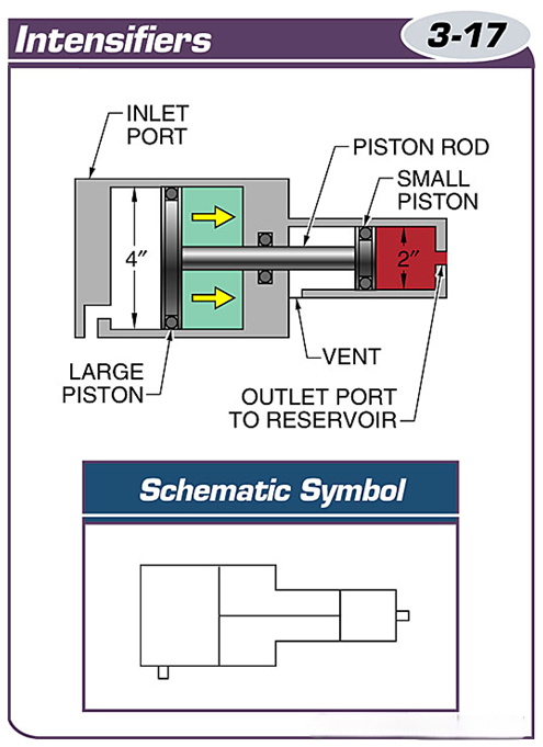
Intensifiers convert low-pressure, high-flow hydraulic oil into high-pressure, low-flow hydraulic oil.
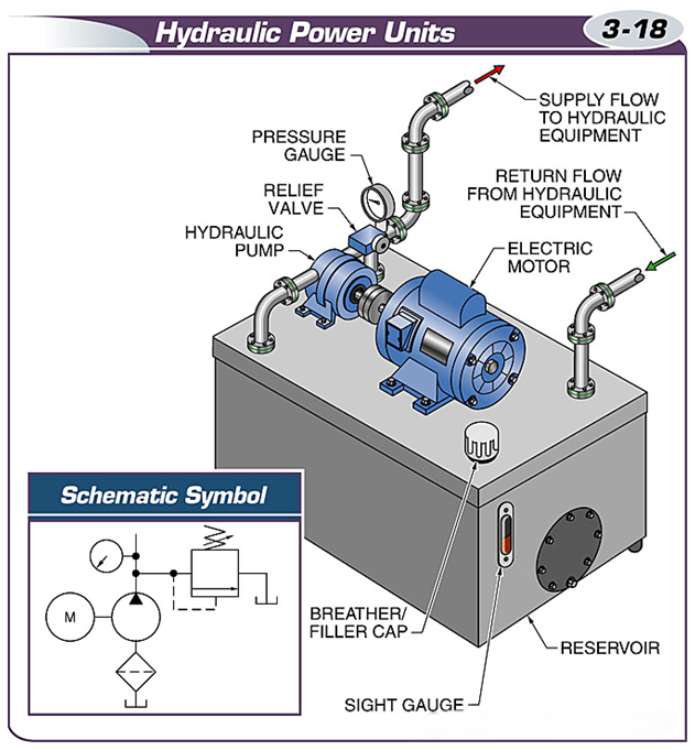
A hydraulic power unit is a self-contained unit that contains all the equipment needed to create fluid flow.
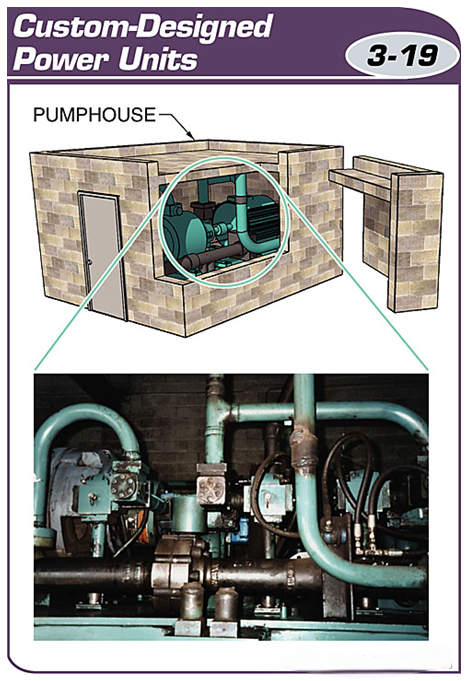
Custom-designed power units are often installed in a separate facility, called a pump room or pump station.
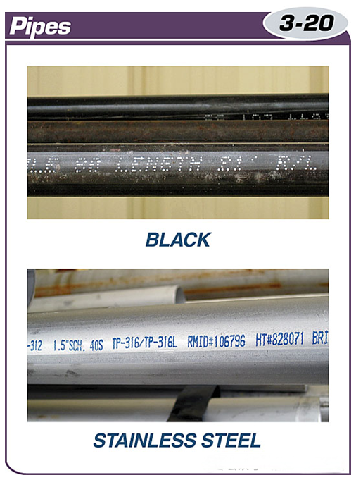
The two types of pipes used in hydraulic applications are carbon steel pipe and stainless steel pipe.
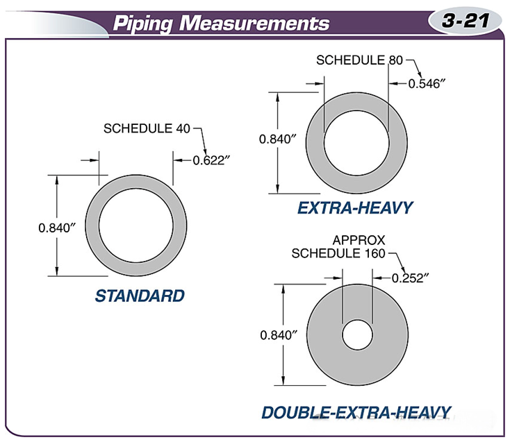
The three common pipe sizes used in fluid power applications are SCH40, SCH80, and SCH160.
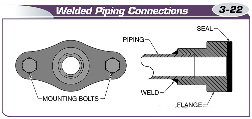
Pipes are usually welded to flanges, which are then bolted together.
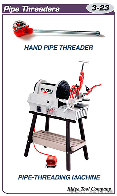
Pipe threading tools are divided into two types: handheld pipe threaders and pipe threading machines.
Metric pipe threads are machined into the ends of the pipe to ensure proper connection with the pipe fittings.
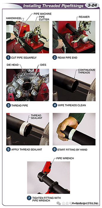
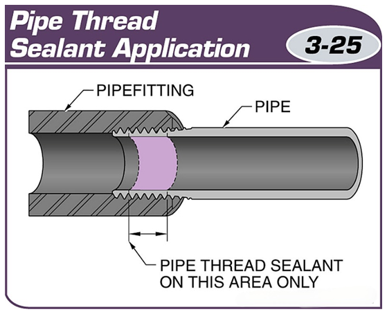
Several threads of the pipe ends are left unapplied with pipe sealant to ensure that there is no contamination of the system.
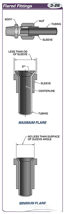
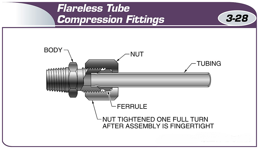
Flared fittings are connected to pipes with flared ends.
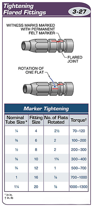
Flared fittings are tightened by turning the fitting nut using a torque wrench or by observing the alignment marks.
Flareless clamp fittings use a circlip to create a seal.
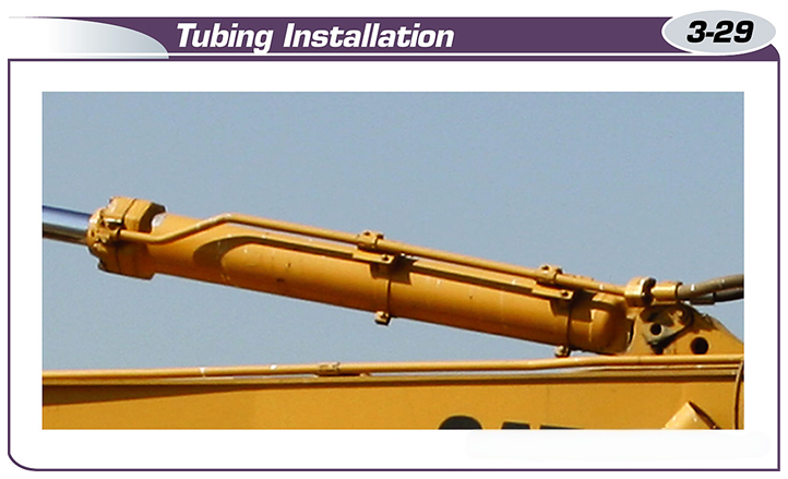
Pipes are usually bent to reduce stress from vibration and to compensate for thermal expansion caused by heating of the fluid.
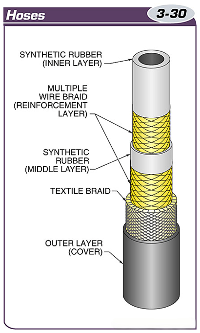
Hoses are made of multiple layers of braids and are used in high-pressure hydraulic systems.
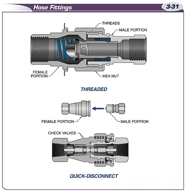
The two types of connection fittings for hoses are threaded fittings and quick-release fittings.
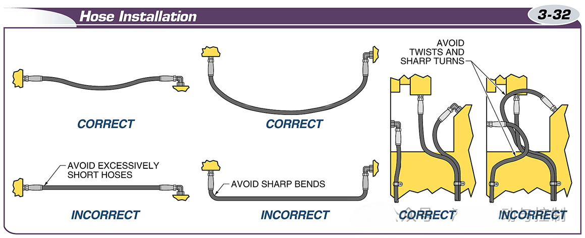
Avoid short lengths, sharp bends, and twists when installing hoses.
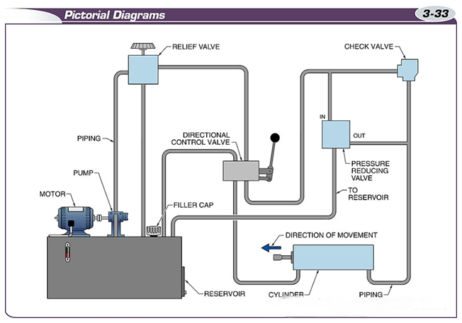
A schematic is a graphic representation that shows how the equipment in a fluid power system is interconnected.
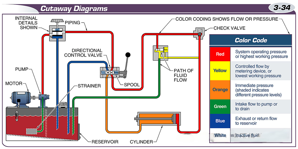
A cross-section view shows the internal details of the components and the flow path of the fluid.
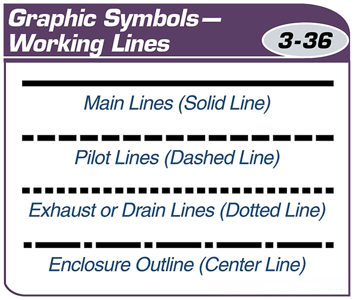
Schematics use standardized lines and shapes and interconnecting lines to represent the function of each component in the system.
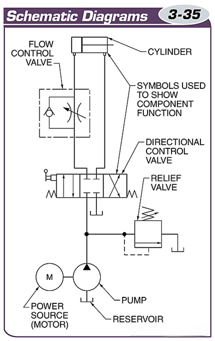
The different types of lines used in schematics are standardized and are used to represent various types of working pipes.